Nutanix and UC - Part 2: Cisco Virtualization Requirements

In the last post I covered an Introduction to Cisco UC and Nutanix. In this post I'll cover UC performance and virtualization requirements.
A scary part of virtualizing Cisco Unified Communications is worrying about being fully supported by Cisco TAC if a non-standard deployment path is chosen. This is due to a long history of strict hardware requirements around UC. When Cisco UC was first released in it's current Linux based incarnation around 2006 as version 5.0 it could only be installed on certain HP and IBM hardware server models. Cisco was VERY strict about hardware revisions of these servers and a software to hardware matrix was made available.
This lead to the creation of a "Specifications" table, listing exact processors, disks, and RAM for each supported server model. When you hear "Specifications Based" or "Spec Based" it all started here.
Customers were welcome to purchase a server directly from HP or IBM that used all of the same hardware components, but the Cisco MCS server (which was just a rebranded HP or IBM server) was recommended. If it was discovered a customer had deviated from the hardware specs listed in the matrix, they could be in an unsupported configuration. If this unsupported configuration was found to be causing a particular problem then a customer might have had to change out the server hardware before further support could be obtained. These calls to technical support were often very stressful and harrowing if it was discovered that the purchasing process for the hardware didn't follow the Spec based matrix exactly.
From a support perspective this makes sense. UC is a critical real-time application and non-standard hardware with less than excellent performance characteristics could cause all sorts of hard to diagnose and hard to troubleshoot problems. Working in support I saw my fair share of these cases where failing disks or problem hardware caused periodic interruptions that only revealed themselves through odd and intermittent symptoms.
UC Performance Needs
Let's take a break from history to look at why performance is so critical to UC.
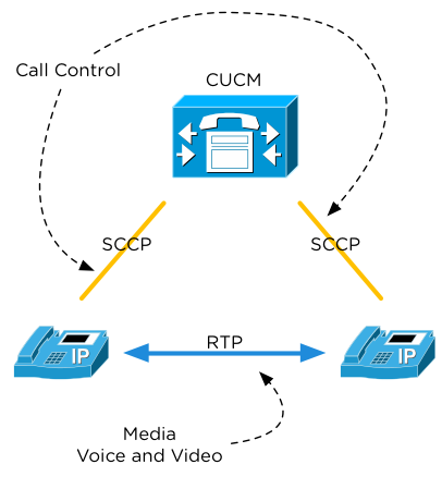
Figure 1 shows where the CUCM Virtual Machine fits into the call path. Each IP Phone will have a TCP session open at all times for call control, sometimes called signaling. Typically in a Cisco environment this is the SCCP protocol, but things are moving to the SIP protocol as an open standard. All the examples below assume SCCP is in use.
The SCCP call control link is used when one phone wants to initiate a call to another phone. Once a call is initiated a temporary media link with Real Time Protocol (RTP) audio/video traffic is established directly between phones. The following process is used to make a phone call.
Basic Phone Call Process
- User goes off hook by lifting handset, pressing speaker, or using headset
- User receives dial-tone
- User dials digits of desired destination and prepares a media channel
- CUCM performs destination lookup as each digit is received
- CUCM sends back confirmation to calling user that the lookup is proceeding
- CUCM sends "New Call" to destination IP Phone
- Destination phone responds to CUCM that it is ringing
- CUCM sends back confirmation to calling phone that the destination is ringing
- Destination phone is answered
- CUCM asks destination phone for media information (IP, port, audio codec)
- CUCM asks originating phone for media information (IP, port, audio codec)
- CUCM relays answer indication and media information to the originating phone
- CUCM relays media information to the destination phone
- Two way audio is established directly between the IP phones
At every step in the above process one or more messages have to be exchanged between the CUCM server and one of the IP phones. There are three places delay is commonly noticed by users:
- Off-hook to dial-tone
- User goes off hook, but CUCM delays the acknowledgement. This leads to perceived "dead air"
- Post dial delay
- User dials all digits, but doesn't receive lookup indication (ringback). This can cause users to hang up. This is EXTREMELY important to avoid because during a 911 call users will typically only wait a second or two to hear some indication that the call is in progress before hanging up. Consider the psychological impact and stress of even momentary dead air during an emergency situation.
- Post answer, media cut-through delay
- Destination phone answers, but audio setup is delayed at the CUCM server. This leads to a user picking up a phone saying "Hello, this is Jason", and the calling user hearing "o, this is Jason".
Also consider that each of the above messages for a single phone call had to be logged to disk. Huge advances have been made in compression and RAM-disk usage, but log writing is still a critical component of a phone call. Call logs and call records are crucial to an enterprise phone system.
Let's look at this at scale.
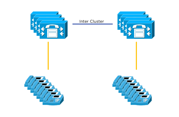
With a cluster of fully meshed call control servers and tens of thousands of IP phones, the situation is slightly more complex. Any single phone can still call any other phone, but now an extra lookup is needed. Where the destination phone registers for call control traffic is now important. Users in the Durham office may be located on a different Call Control server than users in the San Jose office. This means all of the above steps must now be negotiated between two different CUCM servers as well as the two phone endpoints.
CUCM uses Inter Cluster Communication Signaling (ICCS) to do lookups and call control traffic between servers. A problem now on any one server could spell disaster for thousands of users who need to place calls and have immediate response. Any server response time latency will be noticed.
Now that we have some background on why performance is so crucial to a real time communication system, let's get back to the history.
Enter virtualization!
Cisco was slow to the virtualization game with Unified Communications. All the same fears about poor hardware performance were amplified with the hypervisor adding another possibly hard to troubleshoot abstraction layer. Virtualization support was first added only for certain hardware platforms (Cisco MCS) and only with certain Cisco UC versions. All the same specifications based rules applied to IBM servers (by this point HP was out of favor with Cisco).
What everyone knew is that virtualization was actually amazing for Cisco UC - in the lab. Every aspiring CCIE Voice candidate had snapshots of Cisco UC servers for easy lab recreates. Customers had lab or demo as proof of concept or test. Cisco used virtualization extensively internally for testing and support.
A Cisco UC customer wanting to virtualize had two options at this point for building a virtual Cisco UC cluster on VMware.
- Buy Cisco MCS servers (rebranded IBM)
- Buy IBM servers
The Cisco DocWiki page was created and listed the server requirements and IBM part numbers and a few notes about VMware configuration.
To any virtualization admin it should be immediately clear that neither of the above options are truly desirable. Virtualization was supposed to give customers choice and flexibility and so far there was none. Large customers were clamoring for support for Hardware Vendor X, where X is whatever their server virtualization shop was running. Sometimes Cisco UC customers were direct competitors to IBM, so imagine the conversation:
"Hello IBM competitor. I know you want Cisco UC, but you'll have to rack these IBM servers in your data center."
Exceptions were made and the DocWiki was slowly updated with more specifications based hardware.
Cisco UCS as Virtualization Door Opener
Cisco Unified Computing System (UCS) is what really drove the development of the Cisco DocWiki site to include considerations for Network Attached Storage and Storage Area Networks. Now Cisco had hardware that could utilize these storage platforms and best practices needed to be documented for customer success. It also started the process of de-linking the tight coupling between UC and very specific server models for support. Now a whole class of servers based on specifications could be supported. This is largely the result of years of caution and strict requirements that allowed UC and virtualization to mature together. Customers had success with virtualization and demanded more.
UC Virtualization Requirements Today
Today everything about Cisco UC Virtualization can be found on the Cisco DocWiki site. A good introductory page is the UC Virtualization Environment Overview, which serves to link to all of the other sub pages.
In these pages you'll find a number of requirements that cover CPU, RAM, Storage, and VMware. Let's hit the highlights and show how Nutanix meets the relevant requirements.
Oversubscription
This isn't anything Nutanix specific, but it's important nonetheless. No oversubscription of ANY resource is allowed. CPUs must be mapped 1 vCPU to one physical core (ignore HT logical core count). RAM must be reserved for the VM. Storage is recommended to be done with Thick Provisioning, but Thin Provisioning is allowed.
The big one here is 1:1 vCPU to core mapping. This will be a primary driver of sizing and is evidenced in all of the Cisco documentation. If you know how many physical cores are available, and you know how many vCPUs a VM takes, most of the sizing is done already!
CPU Architecture
Specific CPU architectures and speeds are listed in order to be classified as a "Full Performance CPU". The Nutanix home page provides a list of all processors used in all node types. All Nutanix nodes except the NX-1000 series are classified as Full Performance CPUs at the time of this writing. That means the NX-1000 is not a good choice for Cisco UC, but all other platforms such as the very popular NX-3000 are a great fit.
Storage
Nutanix presents an NFS interface to the VMware Hypervisor. The Nutanix Distributed Filesystem backend is seen by VMware as a simple NFS datastore. The DocWiki page lists support for NFS under the Storage System Design Requirements section. There is also a listing under the storage hardware section. Most of the storage requirements listed apply to legacy SAN or NAS environments so aren't directly applicable to Nutanix.
The key requirements that must be met are latency and IOPS. This is another area where calculation from the traditional NAS differs. In the legacy NAS environment the storage system performance was divided by all hosts accessing the storage. In the Nutanix environment each host accesses local storage, so no additional calculations are required as the system scales! Each node has access to the full performance of the NDFS system.
Each UC application has some rudimentary IOPS information that can be found here on the DocWiki storage site. These aren't exact numbers and are missing some information about the type of testing that was performed to achieve these values, but they get you in the ballpark. None of the UC applications listed are disk intensive with average utilization less than 100 IOPS for most UC applications. This shows that again the CPU will be the primary driver of sizing.
VMware HCL
Cisco requires that any system for UC Virtualization must be on the VMware HCL and Storage HCL. Nutanix works very hard to ensure that this requirement is met, and has a dedicated page listing Nutanix on the VMware HCL.
With the above requirements met we can now confidently select the Nutanix platform for UC virtualization and know it will be supported by Cisco TAC. The DocWiki is an incredibly useful tool to know that all requirements are met. Check the Cisco DocWiki frequently as it's updated often!
Cisco UC OVA Files
Before we conclude let's take a look at one more unique feature of Cisco UC and the DocWiki page.
Each Cisco UC application is installed using the combination of an OVA file and an install ISO. The OVA is required to ensure that exact CPU, RAM, and Disk sizes and reservations are followed. All Cisco OVA files can be found here on the DocWiki. Be sure to use these OVA files for each UC application and use the vCPU and RAM sizes from each OVA template to size appropriately on Nutanix. The ISO file for installation is a separate download or DVD delivery that happens on purchase.
In the next post, we'll cover the exact sizing of Cisco UC Virtual Machines and how to fit them onto an example Nutanix block.